Glass 3D Printing Custom Toolpaths
- Tony Koutsonikolas
- Oct 25, 2024
- 2 min read
Updated: Nov 12, 2024
How Complex Can Glass 3D Printed Pieces Become?
The complexity of a glass 3D-printed piece depends on three main factors: hardware, process, and design (specifically, toolpath and part design).
Hardware and Process
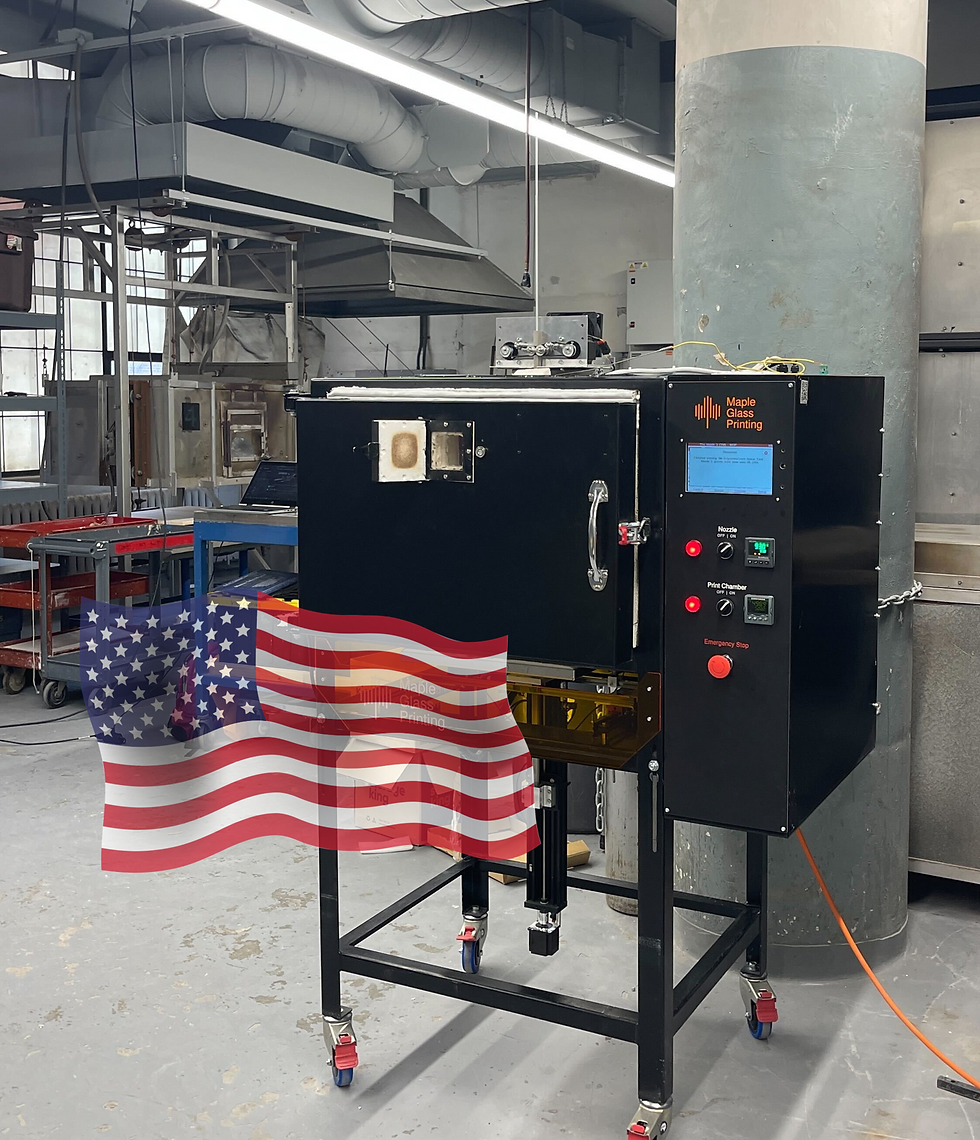
Our glass 3D printing technology, like The Maple 4, uses filament-based printing, which allows for precise control over extrusion. The ability to start and stop extrusion at will is a key advantage in achieving intricate designs.
Given that glass melts at high temperatures, some oozing of material (as seen in polymer printing) is inevitable. However, thanks to The Maple 4's fast travel moves—made possible by its lightweight print carriage—this issue is significantly reduced compared to previous versions. This efficiency opens up new possibilities for more complex glass prints.
Toolpath and Part Design
The toolpath (often referred to as .gcode) that the 3D printer follows plays a crucial role in the complexity of the final part.
Common Approach: Slicing Software
Most commonly, slicing software is used to convert a 3D model into a toolpath, applying various settings like layer height and line width. For example, one of our go-to slicing tools is Prusa Slicer, which helps us optimize the printing process and minimize errors.
A well-designed part can make a world of difference. In one example, a part is designed with a 6mm wall thickness, and the line width is set to 3mm. This means the wall is made of exactly two lines, allowing the part to be printed continuously, which simplifies the process for the printer.
In another example, a part is designed with a 2mm interlacing wall, which exponentially increases the rigidity of the glass. This clever design approach, optimized through slicing, showcases how much strength can be built into a structure with minimal material.
Design Credit: Triple G Workshop, Printables
Advanced Approach: Custom Toolpath Creation
For more intricate designs, custom toolpath creation can be the best solution. This involves manually writing the toolpath, either through code or specialized software like FullControl or Rhino.
In the example below, a custom toolpath was generated using Rhino to create a continuous looped contour.
If a typical slicer had been used, the toolpath would not have been continuous, leading to breaks in the print. By customizing the toolpath, we achieved a smooth, uninterrupted print, showcasing the flexibility of our technology.
The generated code was then sent to Maple Glass Printing, where we successfully produced the part.

Design Credit: Brandyn Callahan and Phirak Suon
Complexity Examples
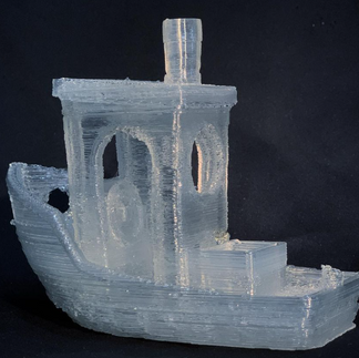
Design Credit: The Blue ring design was produced during an artist residency Maple Glass Printing held. The talented Danielle Colon produced this part (her website is here: www.daniellecolon.com)
Get in touch
If you're working on a project that could benefit from our glass deposition system, don’t hesitate to reach out—we’d love to hear about your work! Contact Us - click here


If there’s one style I always connect with elegance, it’s fashion fonts. They’re stylish, chic, and instantly elevate any design. I’ve used fashion font in mockups for clothing brands, social media posts, and even personal projects, and they never fail to add a sense of class. These fonts are perfect when you need something refined that still feels modern. Anyone working in lifestyle, beauty, or fashion should definitely give them a try.